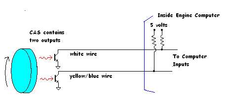
The CAS contains two transistors that are controlled either magnetically or
optically by two spinning arms. These transistors switch the inputs of the engine
computer.
The inputs inside the computer are connected to a 5 bolt power suppply through
resistors. When a transistor is turned on, the signal switched to 0 volts. Otherwise,
it stays at 5 volts.
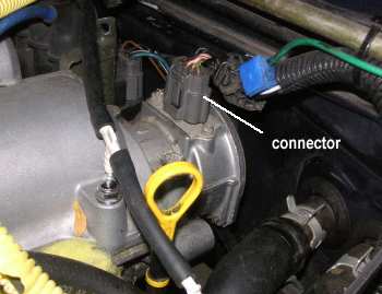
Disconnect the CAS connector and check for voltages on the plug.
 |
 |
|
The CAS connector is by the dipstick on a 1.8 engine. On a 1.6 engine, it's on the other side of the valve cover.
|
|
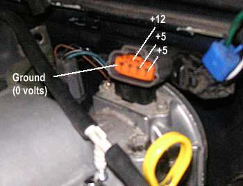 |
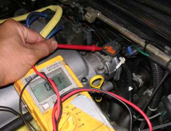
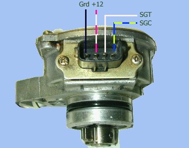
If you don't know how to use a voltmeter, you should not be doing this. With the connector oriented like this (tab up), the normal measurement
is 0 volts, +12 volts, +5 volts, +5 volts. As shown, the black wire in
the harness with be at the left Also check the first pin (black wire) for continuity to ground If the voltages and ground connection check out, the wire harness to the computer is good. |
| Electrical Test - per shop manual | |
 |
 |
|
The factory shop manual shows the above method for testing the CAS. Hook up power and ground. Then you need a load resistor and a 5 volt supply. With a volt meter hooked up to the resistor, you will read either 0 or +5 volts, depending on the position of the CAS rotor. The SGC pin should switch between +5 and 0 volts twice per revolution. |
|
|
Disclaimer: Not a certifed auto mechanic. Not a Mazda technician. The information on this page is my own interpretation and may be flat-ass wrong. Use at your own discretion.
|
|